

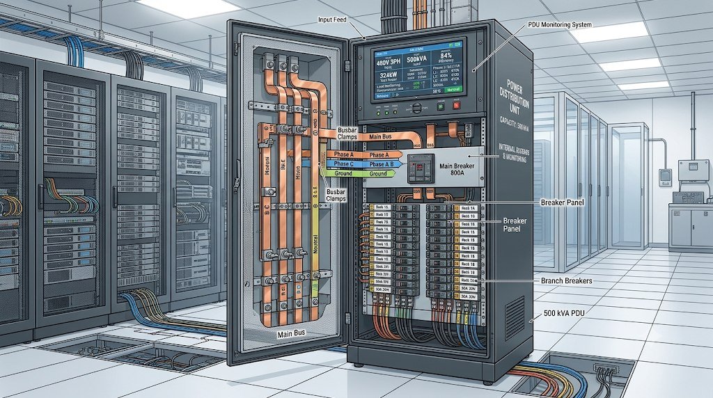

When planning power distribution for a high-density server hall or commercial compute cluster, calculating exact equipment capacity prevents costly design bottlenecks. A 500 kVA PDU (Power Distribution Unit equipped with an internal step-down isolation transformer, primary circuit protection, sub-feed panelboards, and intelligent metering) is one of the highest-capacity floor-standing distribution systems deployed in modern data centers. However, a common mistake among facility planners is assuming that a 500 kVA nameplate rating means you can connect 500 kilowatts (kW) of server equipment.
In real-world electrical engineering, the usable IT load a 500 kVA unit can safely support is governed by three critical factors: the power factor (PF) of your connected server power supplies, the National Electrical Code (NEC) 80% continuous load rule, and N+1 or 2N redundancy architectures. Understanding how these variables interact ensures you never overload main breakers, overheat transformer windings, or strand expensive electrical headroom.
Below is a practical, step-by-step engineering guide breaking down the exact electrical capacity, amperage limits, rack counts, and safe loading thresholds for a 500 kVA floor distribution system.
1. Converting kVA to Usable Kilowatts (kW): Understanding Power Factor
Electrical transformers and distribution units are rated in kilovolt-amperes (kVA)—which represents apparent power—while IT servers consume active (real) power measured in kilowatts (kW).
The relationship between apparent power and active power depends on the Power Factor (PF) of the connected IT hardware:
-
Formula: Real Power (kW) = Apparent Power (kVA) × Power Factor (PF)
Modern enterprise servers equipped with 80 PLUS Titanium or Platinum switch-mode power supplies operate at a very high power factor—typically between 0.95 and 0.99. Older legacy networking gear or mixed facility loads may operate closer to a 0.85 or 0.90 power factor.
Maximum Theoretical Capacity by Power Factor
-
At 0.80 Power Factor (Legacy Industrial Standard): 500 kVA × 0.80 = 400 kW maximum apparent real power.
-
At 0.90 Power Factor (Mixed Data Center Loads): 500 kVA × 0.90 = 450 kW maximum apparent real power.
-
At 0.95 Power Factor (Modern Enterprise Servers): 500 kVA × 0.95 = 475 kW maximum apparent real power.
-
At 0.99 Power Factor (Modern AI / High-Efficiency PSUs): 500 kVA × 0.99 = 495 kW maximum apparent real power.
2. Applying the NEC 80% Continuous Load Safety Rule
While a 500 kVA unit can theoretically supply up to 475 kW to 495 kW at peak, data centers operate 24 hours a day, 7 days a week. Under National Electrical Code (NEC Article 210.20 and 215.3) regulations, any electrical circuit or distribution device carrying a continuous load (defined as running at maximum current for three hours or more) must not exceed 80% of its rated overcurrent protection capacity.
Operating a distribution unit continuously above 80% generates excessive thermal stress inside molded-case circuit breakers, causing nuisance thermal trips and accelerating transformer insulation wear.
Safe Continuous Usable Load Calculation
Applying the mandatory 80% continuous safety limit reduces the maximum design capacity to 400 kVA:
-
400 kVA Safe Continuous Limit × 0.95 Server Power Factor = 380 kW of continuous usable IT load.
-
400 kVA Safe Continuous Limit × 0.99 Server Power Factor = 396 kW of continuous usable IT load.
In practical terms, if you are designing a single-path (N) distribution zone, 380 kW to 396 kW is the maximum continuous server load you should assign to a 500 kVA floor unit.
3. Redundancy Impact: Single-Feed (N) vs. Dual-Feed (2N) Capacity
In mission-critical Tier III and Tier IV facilities, server cabinets feature dual power supplies connected to two completely independent electrical paths (Feed A and Feed B). If one PDU fails or undergoes scheduled maintenance, the second PDU must immediately absorb 100% of the combined rack load without tripping.
Single-Path (N) Deployment Capacity
-
Each cabinet connects to only one PDU.
-
Safe Design Load per 500 kVA Unit: Up to 380 kW (80% continuous limit).
Active-Active Dual-Path (2N) Deployment Capacity
-
Two 500 kVA units work together as a redundant pair (PDU A and PDU B).
-
During normal operation, each unit carries half the load—roughly 190 kW (40% capacity each).
-
During a failover event when one unit goes offline, the surviving unit instantly picks up the full 380 kW (80% continuous limit) safely without exceeding NEC thermal thresholds.
4. Amperage Capacity Across Primary and Secondary Voltages
Knowing the exact current (amperage) flowing through primary input feeders and secondary output busbars is vital for sizing main circuit breakers, feeder cables, and downstream sub-feed panels.
The three-phase amperage formula is: Amps = (kVA × 1,000) ÷ (Voltage × 1.732)
Primary Input Current Ratings (3-Phase)
-
At 480V 3-Phase Input: 500,000 VA ÷ (480V × 1.732) = 601.4 Amps full-load current. Because standard molded-case breakers cannot run continuously at 100% rating, facilities install an 800A main input breaker (80% of 800A = 640A safe continuous limit).
-
At 600V 3-Phase Input: 500,000 VA ÷ (600V × 1.732) = 481.1 Amps full-load current, typically protected by a 600A main input breaker (80% of 600A = 480A safe continuous limit).
Secondary Output Current Ratings (3-Phase)
-
At 208V/120V 3-Phase Output: 500,000 VA ÷ (208V × 1.732) = 1,387.9 Amps full-load current. Because standard panelboards max out around 400A to 800A per bus section, a 500 kVA unit stepped down to 208V requires a 1,600A main secondary bus feeding multiple sub-feed panelboards or row-level Remote Power Panels (RPPs).
-
At 415V/240V 3-Phase Output: 500,000 VA ÷ (415V × 1.732) = 695.6 Amps full-load current. Higher output voltage cuts secondary amperage in half, drastically reducing copper busbar size and cable weight.
5. How Many Server Racks Can a 500 kVA PDU Support?
Using the 380 kW safe continuous usable load benchmark (assuming a 0.95 power factor and 80% NEC derating), facility planners can estimate rack capacity across different compute densities:
Rack Capacity Breakdown by Power Density
-
Low-Density Enterprise Racks (5 kW per rack): Supports up to 76 cabinets in an N configuration, or 38 cabinets per redundant 2N pair.
-
Medium-Density Cloud Racks (10 kW per rack): Supports up to 38 cabinets in an N configuration, or 19 cabinets per redundant 2N pair.
-
High-Density Compute Racks (20 kW per rack): Supports up to 19 cabinets in an N configuration, or 9 cabinets per redundant 2N pair.
-
Ultra-High-Density AI / GPU Racks (40 kW per rack): Supports up to 9 cabinets in an N configuration, or 4 cabinets per redundant 2N pair.
Avoiding Stranded Power via High Pole Counts
Even if a 500 kVA transformer has 380 kW of electrical headroom, you cannot use that power if you run out of physical circuit breaker slots. Low-density enterprise racks require many smaller branch breakers. To support 38 to 76 cabinets without stranding power, ensure your 500 kVA unit feeds multiple high-density sub-feed panelboards (such as dual 84-pole sections providing 168 total poles) or dedicated row-level RPPs.
6. Critical Hardware Factors That Affect Usable Capacity
Two different 500 kVA distribution units can deliver vastly different real-world load capacities depending on internal component quality. Cheaply built units often require manual derating—forcing you to run them at 60% or 70% load instead of 80%—to avoid overheating.
K-Factor Harmonic Withstand (K-13 or K-20)
Switch-mode server power supplies draw current in non-linear pulses, creating third-order triplen harmonics that add together on the neutral wire instead of canceling out. If a 500 kVA unit uses a cheap K-1 industrial transformer, harmonic heating will force you to derate its capacity significantly.
Always specify a K-13 or K-20 rated isolation transformer built with 100% electrolytic copper windings, electrostatic shielding, and a 200% double-sized neutral busbar. This ensures the unit handles full 80% continuous server loads without neutral overheating.
Vendor-Agnostic Multi-Brand Breaker Busbars
To utilize all 380 kW of continuous capacity, your sub-feed panelboards must be populated with the exact branch breakers your racks require. Traditional OEMs lock panelboards to a single proprietary breaker brand; if that brand faces a 30-week supply backlog, your 500 kVA unit sits partially empty.
Specifying vendor-agnostic breaker busbars (such as OpenSelect architecture) allows panelboards to accept UL-listed circuit breakers from multiple major manufacturers—including Schneider Electric, Siemens, Eaton, and ABB—interchangeably. Contractors can populate panels immediately using available breaker stock, unlocking 100% of your usable capacity on schedule.
Capacity Planning Reference Matrix
Use this quick-reference guide when sizing a 500 kVA distribution zone:
-
Nameplate Apparent Power: 500 kVA
-
Safe Continuous Apparent Power (80% NEC Rule): 400 kVA
-
Usable Continuous Real Power (at 0.95 PF): 380 kW (Single N) / 190 kW per unit (2N Redundant)
-
Primary Main Input Breaker (at 480V 3-Phase): 800 Amps
-
Secondary Output Current (at 208V 3-Phase): 1,388 Amps full load (1,110 Amps at 80% continuous)
-
Required Transformer Core Rating: K-13 or K-20 with 100% copper windings and 200% neutral busbar
Frequently Asked Questions
Why can’t I run 500 kW of servers on a 500 kVA PDU?
First, kVA measures apparent power while servers consume real power measured in kW; multiplying 500 kVA by a typical 0.95 server power factor yields 475 kW. Second, National Electrical Code (NEC) safety regulations restrict continuous loads running three hours or longer to 80% of rated capacity, bringing the safe continuous IT load limit to roughly 380 kW.
What size main input breaker is needed for a 500 kVA PDU at 480V?
At 480V three-phase power, a 500 kVA unit draws 601.4 Amps at full load. Because standard molded-case breakers are rated for 80% continuous operation, an 800-Amp main input breaker is required (80% of 800A equals 640A, safely covering the 601.4A full-load draw).
How much load should each 500 kVA PDU carry in a 2N redundant setup?
In an active-active 2N redundant architecture where two 500 kVA PDUs power dual-corded racks, each PDU should carry no more than 40% of its nameplate capacity (around 190 kW) during normal operation. This guarantees that if one PDU goes offline for maintenance or due to a fault, the surviving unit can absorb 100% of the combined load (380 kW) without exceeding the 80% continuous safety limit.
Does stepping down to 415V instead of 208V increase the kW capacity of a 500 kVA PDU?
The total kilowatt capacity remains 380 kW continuous regardless of output voltage. However, stepping down to 415V/240V cuts secondary output current nearly in half compared to 208V/120V (695 Amps vs. 1,388 Amps), reducing copper cable sizes, lowering resistive heat losses, and freeing up physical breaker space inside sub-feed panelboards.
How does a K-20 rating protect the usable capacity of a 500 kVA unit?
High-density server power supplies generate harmonic currents that cause severe core and neutral heating. Without a K-13 or K-20 rated transformer and a 200% rated neutral busbar, facility engineers must artificially derate the PDU’s load limit to prevent thermal insulation failure. A K-20 rating preserves the full 380 kW continuous operating envelope.
Maximizing the safe electrical capacity of a high-output floor distribution unit requires balancing electrical code safety margins, server power factor curves, redundancy failover math, and internal thermal engineering. By accounting for the 80% continuous load rule, specifying 100% copper K-rated isolation cores, and utilizing multi-vendor breaker busbars that prevent stranded pole capacity, facility managers can confidently deploy up to 380 kW of continuous compute power per unit. When engineering high-capacity distribution zones for growing AI and cloud environments, build your electrical backbone with custom floor distribution systems manufactured by Voltz for reliable mission-critical performance.